Skip to technical content
Mainrich International
Humanoid robotics / joint actuator magnets

Joint actuator magnets.Specified joint by joint.

Humanoid robot joint actuators typically use high-coercivity NdFeB arc segments or radial multipole rings in frameless torque motors, plus low-deviation ring or disc magnets for encoder feedback. A typical platform contains about 28 to 40 motors, so grade, pole geometry, harmonic-drive envelope, and inspection plan must be set for each joint class.

28 to 40motors per platform
Ring / arcrotor magnet paths
Per drawingsensor deviation
PPAP L3qualification path
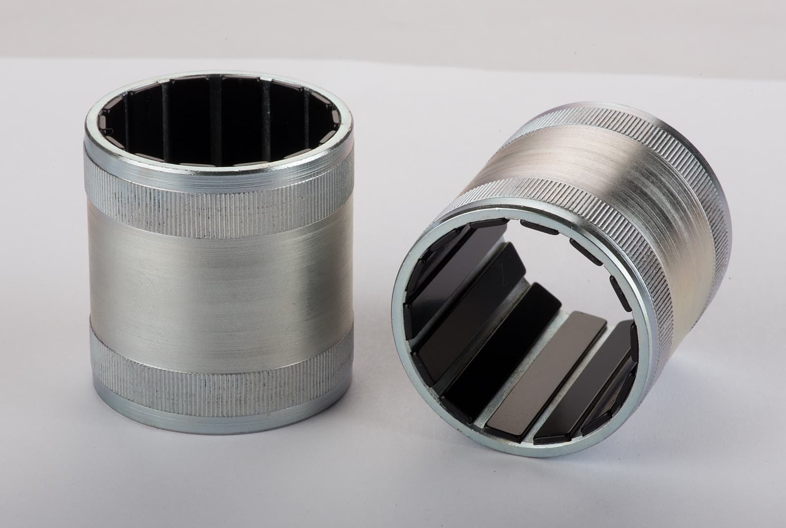
Real rotor assembliesMatched arc magnets installed in two machined rotor housings
Segmented rotor assembly / product referenceMatched arc magnets seated in machined cylindrical housings.
Drawing review · Documentation scope confirmed for the order · Human response within 1 business day
ENGINEERING SUMMARY

Four decisions set the actuator magnet path.

  • Per designmotors per humanoid

    Joint classes need separate decisions for torque, heat, geometry, and feedback.

  • Ring or arcrotor architecture

    Radial multipole rings and matched arc segments cover different tooling and assembly paths.

  • Per drawingsensor deviation

    Specify the angular limit, measurement method and sampling in the control plan.

  • PPAP L3qualification route

    Confirm the supplying plant and applicable certificate and submission scope.

Start the joint review

Send the rotor section and duty cycle.

Mainrich reviews the magnetic circuit together with the motor, bearing, encoder, and harmonic-drive interfaces before defining the magnet and inspection plan.

01Rotor ID, OD, stack length, pole count, and air-gap target
02Joint type, peak torque, duty cycle, and worst-case magnet temperature
03Encoder geometry, feedback target, prototype quantity, and annual volume

Engineering response within 1 business day. Pricing within 2 business days.

Robotics magnet RFQ

Fields marked * are required
PDF, STEP, IGES, DXF, DWG, or ZIP

Reviewed for geometry, magnetization, traceability, and qualification.

01 / JOINT ARCHITECTURE

Treat the motor, gearbox, and encoder as one stack.

Harmonic-drive integration compresses the motor, bearing, gearbox, and position feedback into one joint envelope. Rotor concentricity, pole placement, adhesive gap, and encoder field angle therefore need one drawing-led review.

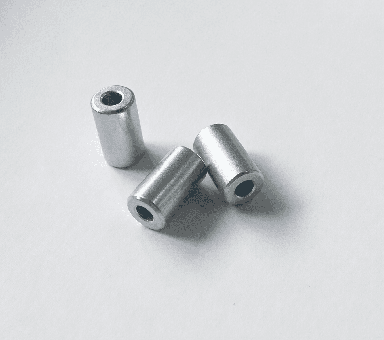
Three finished ring magnets on a white inspection surface
Ring geometry / real product referenceFinished ring magnets for drawing-specific magnetization.
Joint actuator control ledgerDrawing-led review
Motor platformFrameless torque motor
Transmission interfaceHarmonic / strain-wave drive envelope
Rotor pathRadial multipole ring or matched arc set
Pole patternDrawing-specific count and orientation
Encoder targetDiametric ring, disc, or multipole target
Sensor deviationAngle and sampling per control plan
QualificationSubmission scope agreed for the production route
The magnet drawing should follow the complete actuator stack, not a nominal rotor diameter.

Mainrich can deliver individual magnets or a bonded rotor sub-assembly. Review the finished magnet assembly path when adhesive selection, hub fit, magnetization, and balancing need one accountable release plan.

ROTOR PATHS / RING OR SEGMENTS

Choose the architecture before tooling.

A radial ring and a segmented rotor can meet the same torque target through different manufacturing, magnetization, and assembly routes. Volume and qualification strategy matter as much as the first prototype.

Real NdFeB product family including rings, arcs, blocks, and assemblies
Compact high-pole-count path
RADIAL MULTIPOLE RING

One ring, controlled pole pattern.

A single ring removes segment gaps and can simplify concentric assembly in compact frameless motors. Pole count, skew, waveform, and post-magnetization inspection are defined against the finished joint geometry.

Best fit
Compact high-pole-count joints
Control point
Waveform + pole position
Release
Flux map + traceability
Review the robotics magnet program
Matched arc magnet segments installed in machined rotor housings
Flexible rotor tooling path
MATCHED ARC SEGMENTS

Segment geometry follows the air gap.

Precision-ground arc segments support a wide diameter range, prototype iteration, and drawing-specific pole layouts. Matched sets control dimensional and magnetic variation before bonding into the rotor.

Best fit
Prototype through serial supply
Control point
Arc fit + flux matching
Assembly
Bonded set or finished rotor
Review rotor assembly capability
02 / DUTY CYCLE + TEMPERATURE

Select coercivity from the hot joint.

Temperature class follows the hottest credible rotor condition, including continuous load, peak current, limited airflow, and heat conducted from bearings and the gearbox. The class ceiling still needs design margin.

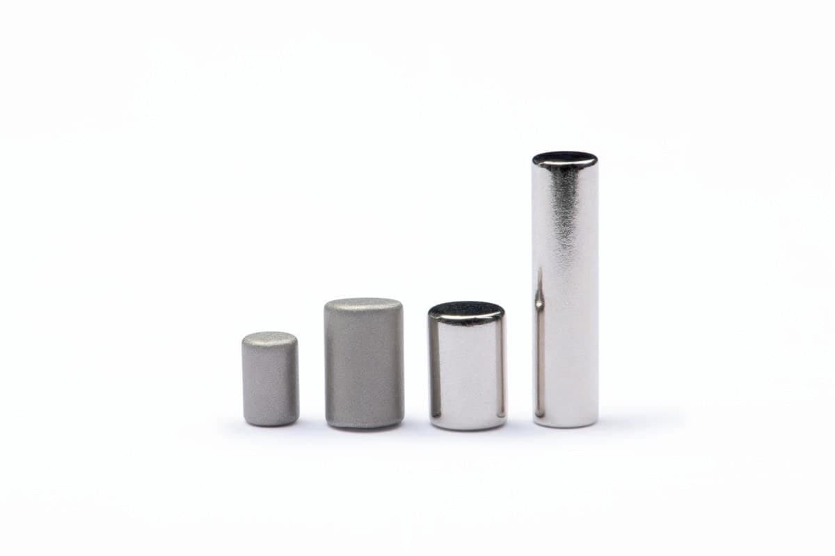
Real sintered NdFeB magnets across several coatings and shapes
Grade and coating selection follows the joint environment.
Controlled thermal envelopeM / H: 100°C / 120°C class
Continuous joint dutySH: 150°C class
High-load or sealed jointUH / EH: 180°C / 200°C class
Verified GBD case / 0.35% Tb surface coating

Reported N45H specimen comparison: Hcj 17.67 to 26.55 kOe; Br 13.62 to 13.61 kGs.

Hcj +50%Verified coercivity increase
17.67 to 26.55 kOeMeasured Hcj result
Br essentially unchangedAt the reported precision
13.62 to 13.61 kGsBr in the reported N45H specimen comparison
03 / CONTROL PATH

Release the motor magnet and feedback target together.

Mechanical inspection, magnetic mapping, encoder-axis control, and PPAP evidence are connected to the same drawing revision and qualification plan.

Coordinate measuring machine probing finished NdFeB magnets at a network plant
STEP 01 / DIMENSIONAL RELEASE

Verify the air-gap surfaces.

Bore, OD, thickness, arc profile, concentricity, and mating features are inspected against the agreed drawing and tolerance plan.

CMM recordsDrawing revisionMatched sets
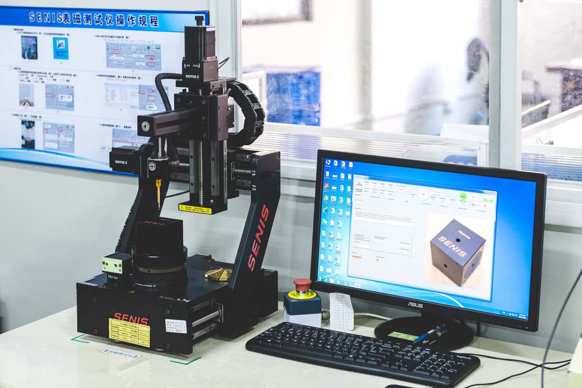
Field mapping station measuring a finished magnet at a network test lab
STEP 02 / MAGNETIC RELEASE

Map the torque and feedback fields.

Rotor pole output and encoder angle are assessed at agreed positions. The control plan defines the measurement method, sampling and acceptance limits.

Flux mappingPole positionAgreed sensor inspection
STEP 03 / PPAP RELEASE

Agree the required submission documents.

Include the required submission level and quality documents in the RFQ. We confirm the applicable production-plant certificate and its scope for the programme.

PPAP Level 3Production-plant scopeLot traceability
MAINRICH RESPONSIBILITY

One accountable engineering and quality path.

Mainrich engineers and quality-controls the program across the four-site production network Mainrich holds equity stakes in.

ENGINEERING FAQ

Before the actuator drawing is released.

These are the decisions that most often change grade, geometry, inspection, or assembly scope.

Which magnet geometry is used in a humanoid joint actuator?

Frameless torque motors commonly use a radial multipole ring or a matched set of arc segments. The choice depends on rotor diameter, pole count, air-gap target, tooling plan, assembly method, and annual volume. Encoder feedback normally uses a separate ring or disc magnet with its own pole-position specification.

Are radial multipole rings always better than arc segments?

No. A single radial multipole ring can improve concentricity and remove segment gaps, while arc segments offer greater tooling flexibility and a practical path across more rotor diameters. Mainrich reviews both architectures against the motor and harmonic-drive tolerance stack before recommending one.

How is the temperature class selected for a robot joint?

Selection starts with the peak magnet temperature, duty cycle, motor load line, peak-current demagnetizing field, and cooling path. The class rating is a material ceiling, not a target rotor temperature, so the final grade needs working margin under the worst credible joint cycle.

Can Mainrich supply encoder magnets for joint feedback?

Send the encoder geometry, pole count, sensor position, air gap and required field waveform. The angle limit, measurement method and sampling are agreed for the proposed part.

Is PPAP Level 3 available for humanoid actuator programs?

Include the required submission level and customer-specific requirements in the RFQ. The applicable production-plant certificate, scope and documents are confirmed for the programme.

Put the complete joint envelope on the table

Get one magnet, assembly, and inspection path.

Send the motor section, joint duty cycle, encoder target, and annual volume. An engineer responds within 1 business day. Pricing follows within 2 business days.