
In this article
Key takeaways
- In a 12-pole, 18-slot motor measured on one stator, a rotor of two pre-magnetised sintered blocks per pole had peak cogging of 80 mNm, 11% of rated torque, while a one-piece bonded Halbach ring had 5.5 mNm, 1% (Zhu, Xia and Howe, IEEE Transactions on Magnetics, 2002).
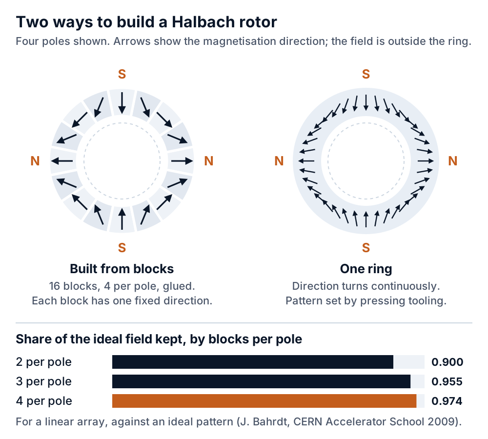
- For a linear Halbach array with M blocks per period (two poles), the fundamental field is scaled by sin(π/M)/(π/M): 0.900 at two blocks per pole, 0.955 at three and 0.974 at four. Rings of flat-sided blocks lose a little more.
- In the same paper's finite-element results, two blocks per pole gave cogging about as large as radially magnetised magnets on back iron, which gives up most of the reason to build a Halbach rotor.
- Block rotors cost you assembly: magnetised blocks repel each other out of place, gaps and glue lines add up, and adhesive can age.
- A one-piece sintered ring has its orientation set when it is pressed and is magnetised in a fixture of its own, so the pole pattern is fixed by tooling. It is also one conductive loop, so eddy current loss needs checking at high electrical frequency.
01
The measured difference
In 2002, Z. Q. Zhu, Z. P. Xia and D. Howe built two Halbach rotors for the same 12-pole, 18-slot motor and measured them on one stator (IEEE Transactions on Magnetics, September 2002). One rotor was made of pre-magnetised sintered blocks, two per pole.
The other was a single injection-moulded bonded ring magnetised in a Halbach pattern. Peak cogging torque was 80 mNm, 11% of rated torque, for the block rotor and 5.5 mNm, 1%, for the ring. The ring motor also ran at a higher efficiency. The two rotors were not the same magnet. The ring was bonded material with a remanence of 0.6 T and 4.6 mm thick; the blocks were 1.0 T and 2.4 mm thick, sized to give the same torque.
The ring needed nearly twice the magnet thickness. Cogging also depends heavily on the slot and pole combination, so the 11% and 1% belong to this motor. The paper's finite-element results matter more for a robot joint, where cogging is felt at low speed. With two blocks per pole, the predicted cogging torque was "similar in magnitude to that which results with radially magnetized magnets" (a radial rotor on back iron, modelled but not built). At that block count most of the reason to build a Halbach rotor is gone.
02
How many blocks per pole
A Halbach rotor made of blocks approximates a field direction that should turn continuously. J. Bahrdt gives the factor for a segmented linear array as sin(π/M)/(π/M), where M is the number of magnets per period, and one period is two poles (CERN Accelerator School 2009, proceedings 2010). Worked through:
- Two blocks per pole (M = 4): 0.900 of the ideal fundamental field.
- Three blocks per pole (M = 6): 0.955.
- Four blocks per pole (M = 8): 0.974.
Key insight
These figures compare a segmented array with an ideal Halbach array of the same magnet and no iron. For a ring of flat-sided blocks Bahrdt gives Halbach's 1980 formula, which adds a geometry term. They allow for gaps through a filling factor but not for angle errors, so ask for the field of your own rotor at your own gap.
03
Field is not the whole answer
Going from two to four blocks per pole adds only about 8% to the fundamental. What it changes more is the shape of the field. Segmentation adds harmonics at fixed orders, and more pieces push the first unwanted one higher (Bahrdt). Zhu and his co-authors found that with two blocks per pole the air-gap field and the back-EMF were "much less sinusoidal than that with four or more", and that more blocks per pole improve the field "albeit increasing the cost of fabrication" (2002).
Our view: if the reason for a Halbach rotor is a smooth joint at low speed, start at four blocks per pole or buy a ring. Three is a compromise worth modelling, and on the 2002 results two rarely repays the assembly work.
04
What assembling blocks involves
Block rotors are usually built from blocks magnetised before assembly (Zhu et al., 2002), and that is where the trouble starts. Neighbouring blocks have different magnetisation directions and push each other out of place. One patent for an assembly method describes blocks that are "easily reversed due to the repulsive magnetic force" and sets out to avoid "large accumulated tolerance, gaps between magnets, wrong polarity and easy deformation" with a positioning cylinder, a pressed sleeve and an anaerobic adhesive (US 11,587,728 B2, 2023).
Another patent notes that the adhesive adds cost and "may fail over time" (US 11,894,184 B2, 2024). The piece count grows fast. Ananthanpillai and co-authors took as their baseline a 16-pole electric vehicle motor whose rotor, with four blocks per pole and axial splits, came to more than 2,000 pieces, and wrote that gaps between neighbouring segments degrade performance (IEEE IEMDC, 2023).
A small actuator rotor has far fewer pieces, but each one still needs placing, gluing and checking for polarity. Tolerance shows up in the field. In Zhu's motor the difference between predicted and measured waveforms for the two-blocks-per-pole rotor came mainly from assembly tolerances. The magnetisation angle of each block also varies.
For accelerator magnets built from blocks, the CBETA design report gives makers' angle tolerances of ±5 down to ±0.5 degrees, with the tighter end costing extra grinding and re-magnetising (arXiv, 2017).
05
How a one-piece ring is made
There are two main routes, and they give different magnets. Bonded rings are moulded from NdFeB powder in a binder. An isotropic bonded ring can be impulse magnetised into a Halbach pattern after moulding. An anisotropic bonded ring has its powder aligned in a Halbach field during moulding and is magnetised afterwards; a 2000 paper by Zhu and co-authors gives about 1 T to align the powder and about 3 T to magnetise it (IEEE Transactions on Magnetics, 2000).
Bonded rings have lower remanence than sintered blocks, which is why the 2002 ring was nearly twice as thick. Sintered rings, usually sold as polar-anisotropic rings, are pressed in a multipole orienting field, sintered, ground and then magnetised (US 4,990,306).
The orientation has to be right at pressing, because it is "difficult to reorient magnetic powder in the magnetization step" (US 6,992,553 B2). So the pole count and pattern are set by the pressing tooling and the magnetising fixture, and changing them means new tooling for both.
Sintered rings oriented this way are also prone to cracking during sintering, and the same patent describes polar-anisotropic arc segments as a route between blocks and a full ring (US 9,646,751 B2). Ask whoever makes them about yield. We supply integrated Halbach rings as a single sintered NdFeB body by a net-shape route.
A stated ±0.02 mm critical-feature capability for that route requires confirmation per feature and drawing, and dimensions and grade are confirmed for each drawing. Our historical surface scans of radial and integrated Halbach rings of the same size are in the ring construction article; they compare specimen fields at the outer surface, not motor performance.
06
Which to choose
Blocks make sense while the design is still moving. If you are building a handful of prototype rotors and the pole count or magnet thickness may change, blocks let you change them without new pressing or magnetising tooling. Plan on four blocks per pole if cogging matters, a fixture that holds every block against the repulsion, and a polarity check on every rotor.
A one-piece ring makes sense once the design is fixed and the quantity is real. It removes the glue lines and replaces the per-block angle error with the orientation quality of the pressing. The published measurement of smoother cogging is for a bonded ring; for a sintered ring, ask for the field data.
The cost moves into tooling and into agreeing the field target and how it is measured. Watch eddy current loss with a one-piece sintered ring. It is one conductive loop that cannot be split. The 2023 IEMDC paper notes that magnets in high-speed machines are usually split into many pieces to keep eddy current loss and heating down, and that its continuous bonded rotor had virtually no eddy current loss (Ananthanpillai et al.). For a slow direct-drive joint the loss may be small; for a fast geared actuator, have it modelled before you commit.
07
Back iron and retention
An ideal Halbach pattern is "essentially self-shielding", so the rotor back iron is not essential (Xia, Zhu and Howe, 2004). The same paper notes that when the magnet is radially thin, back iron still adds air-gap field and torque. A rotor of a few blocks per pole is not ideal: the segmented baseline in the 2023 IEMDC paper had field at the back of the array and still needed back iron.
Model your own thickness and block count before you take the iron out. At speed the magnets need holding against the spin, whichever route you take. In the 2023 paper, for a machine with a maximum speed of 20,000 rpm, both the segmented baseline and the authors' continuous bonded replacement needed a carbon fibre wrap. Sintered NdFeB is brittle, and a crack in a one-piece ring affects the whole ring.
08
What to put on the drawing
For either route: pole count, the orientation pattern, skew if any, and a phase reference. A field target with the measurement radius or gap, probe direction and how acceptance is judged. Top speed and electrical frequency, the magnet temperature limit, the retention method and balance needs. Coating and the environment.
Prototype and production quantities. For blocks, add the number of blocks per pole, the magnetisation direction of each block and the angle tolerance you need. For a one-piece ring, say whether a sintered or bonded ring is acceptable, since the remanence, wall thickness and eddy current loss differ.
FAQ
Frequently asked questions
How many magnets per pole does a Halbach rotor need?
For a linear array, four blocks per pole keeps about 97% of the ideal fundamental field (sin(π/8)/(π/8) = 0.974), against 90% at two. In finite-element results from a 2002 IEEE paper, two blocks per pole gave cogging about as large as radial magnets on back iron. We would start at four blocks per pole, or use a one-piece ring, when smooth torque matters.
Is a one-piece Halbach ring better than a segmented rotor?
In one 12-pole, 18-slot motor, Zhu, Xia and Howe measured peak cogging of 1% of rated torque with a one-piece bonded ring against 11% with two sintered blocks per pole, and the ring motor was more efficient. The ring was thicker because bonded material is weaker. A one-piece sintered ring has its pattern fixed by tooling and needs its eddy current loss checked at high speed, so it suits a fixed design better than a prototype.
Does a Halbach rotor need back iron?
An ideal Halbach pattern is essentially self-shielding, so back iron is not essential. When the magnet is radially thin, or the rotor has only a few blocks per pole, back iron can still add field or be needed to carry flux leaking at the back. Model your own design.
Why is assembling a segmented Halbach rotor hard?
The blocks are magnetised before assembly and push each other out of place, so a fixture is needed. Gaps, glue lines and each block's magnetisation angle add up across the rotor, and published patents note that adhesive adds cost and can fail over time.
Send your Halbach rotor drawing, or the pole count, size and field target, and a person replies within 1 business day.